Modelling a Screwdriver in Art of Illusion

by Julian MacDonald (feel free to email comments and suggestions)

Written: September 2003 for v 1.6


In this tutorial, we will look at using the Triangle Mesh editor to create a screwdriver. The tutorial illustrates the use of the Bevel/Extrude tool and various other triangle mesh functions.

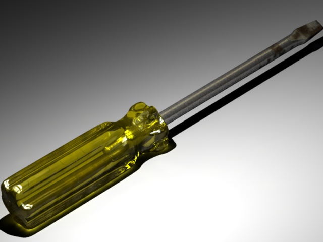
Before we start, just so you know whether or not to bother, this is the screwdriver we will be modelling:


OK, time to model...


Modelling the Handle


Modelling the Blade


Texturing and Rendering

Texturing the Handle

Texturing the Screwdriver Blade


THE HANDLE

We'll start off creating the cross section for the screwdriver handle using the Polygon tool. We need to apply a bit of thought before we launch in and start modelling. The first thing to consider is how many points we need in the polygon. This depends on the complexity of the cross-section. The one I am modelling in this tutorial has a kind of hexagonal cross-section but with squared sections at each of the 6 hexagon 'points'. So for each 'point' of the hexagon, I'm going to need 4 vertices to describe the square. Therefore double-click on the Polygon icon and enter 24 for the number of sides. It's a smooth-looking handle so choose 'Approximating' for the shape. Click OK to set these parameters. Every time you use the polygon tool from now on, you will get a 24 point Approximating polygon until you change the defaults.

To actually draw the polygon, click once on the icon. Now, while holding down the shift and crtl keys (shift to get a uniform shape, ctrl to produce a filled polygon), drag out the polygon onto the Top viewport. You should end up with something like that in pic 1 below:

Looks a bit like a circle at the moment but that will change. Open the polygon in the triangle mesh editor by double-clicking on the object in the Object List or selecting the polygon and going to Object -> Edit Object. The first thing to do is to scale down every other pair of vertices. So select them as shown in Pic 1 and use the scale tool with shift and ctrl pressed (shift for a uniform scale, ctrl for a centred scale) to shrink them toward the centre to give the result shown in Pic 2.


Now it's starting to look more like a hexagon. The next thing is to widen the hexagon 'points'. You can do this in pairs by selecting the points shown in Pic 3 and using the scale tool again - this time don't press shift when scaling as we only want to scale in one axis. Do use the ctrl, though to get a centred scaling. Now rotate the camera to get the next pair of points at the top and bottom of the view. This is easily done by holding the Alt and shift keys while dragging with the left mouse button (the shift constrains the rotations to the axis going into the screen plane). So spin the camera around to get the next hexagon point at the top and bottom of the polygon, select both pairs of points and scale again. Repeat for the last pair of pairs to get the result shown in Pic 4.

Now to widen the indented sections of the hexagon. Select the points shown in Pic 4 and use the scale tool again to stretch them out. Repeat for the other parts of the polygon and you should end up with the final cross-section shown in Pic 5. Press OK to leave the triangle mesh editor

Now to make it 3D! We do this with the Extrude tool. Make sure the polygon is selected and go to Tools -> Extrude. This will display a dialogue similar to that shown on the right:

Change the Extrude Direction to Y and a Distance of 1. This will give us the central portion of the handle as shown in Pic 7 below.

Now to model the bottom of the handle. Select the faces on the bottom of the model as shown in Pic 7 and click on the Bevel/Extrude tool . Dragging on the viewport will generally apply both an extrude and a bevel in one operation making for a speedy workflow. Dragging left/right bevels and dragging up/down extrudes. You can constrain this tool to just do an extrude or just a bevel by holding shift while dragging in the appropriate direction. For the bottom of the handle, we want the area of the faces to reduce down smoothly so we require both bevel and extrude. So, drag upwards and to the right to extrude and bevel simultaneously by the amounts shown on Pic 8. Repeat this operation with a smaller extrude to round off the end as shown in Pic 9.


Now in reality the bottom of the handle actually has a circular cross-section rather than a hexagonal one. So, we need to alter the cross section appropriately at this stage. Switch to a bottom view as shown in Pic 10. Pull the points in the lowest 'hexagonal' cross section around to form a circle as shown in Pic 11.


Now select the faces at the now circular bottom (Pic 12) and bevel/extrude twice more to get a nice rounded circular base as shown in Pic 13.


Now to work on the top. Select the faces at the top of the model (Pic 14) and bevel/extrude again as shown in Pic 15.


Now the cross section of the screwdriver becomes circular at this point so switch to a top view (Pic 16) and move the vertices we just created to a circular cross-section as we did before to get something similar to Pic 17. Don't worry that it doesn't look circular at this point -that's just to do with the smoothing


Now carry out a few more bevel/extrusions to get the shape shown in Pic 18. As the handle widens out again, we need to go back to a hexagonal cross-section so move vertices at the top until we get the shape back again (Pic 20).


Move the top section of vertices down to get a sharper change in cross-section as shown in Pics 21 and 22.


Use the Bevel/Extrude tool again to Extrude straight up (hold down Shift while dragging up to constrain to an extrude only) as in Pic 23. Repeat this for a very small extrude and then move the points at the top to go back to a circular cross-section again (last time, I promise!) as shown in Pic 24. Perform a bevel only by holding down Shift and dragging to the right as shown in Pic 25. Then extrude the faces up a bit more to get something similar to Pic 26.


Now to add the bore hole for the blade. Bevel inwards to slightly larger than the radius of the bore hole (Pic 27). At this point you may need to move the points around a bit to get a nicely spaced set of vertices around the circle (Pic 28). Now bevel in a little more to the bore hole radius (Pic 29). Then extrude downwards a small amount (Pic 30). These small movements help keep the surface smooth around the bore hole.


Extrude into the body of the handle to the length of the bore hole (Pic 31) and then bevel/extrude a small amount to get a well-defined end (Pic 32.


THE BLADE


Modelling the blade seems like an easy thing to do but it actually requires some thought ! Again we're going to start off with a filled polygon and so need to consider the number of points. The cross-sectional shape is again our clue in how many we're going to need - look at the most complex part of a flat screwdriver blade. I reckon we'll need 12 points so double-click the polygon tool icon and set Sides to 12 and Shape to Approximating and click OK. Then create a filled uniform polygon in the Top view by holding Ctrl and Shift while dragging with the left mouse button depressed. This produces the polygon shown in Pic 34. Now extrude this polygon via Tools -> Extrude; set the Extrude Direction to Y and Distance to about 3. Clicking OK should give you the shape shown in Pic 34. Open this in the triangle mesh editor, select the top set of faces as shown and use the Bevel/Extrude tool to extrude only (hold down the Shift key while dragging up) these faces 3 times as shown in Pic 35.


In Front view, select the points shown in Pic 36 - this includes the points at the back as well. Select the Taper tool and taper out the top by holding Ctrl and dragging one of the top handles outwards slightly as shown in Pic 37. Now select the points shown in Pic 38 i.e. one in from the last selection (front and back), and repeat the taper operation to get the result shown in Pic 39. Select the central columns of points shown in Pic 40 (front and back) and taper those to get Pic 41.


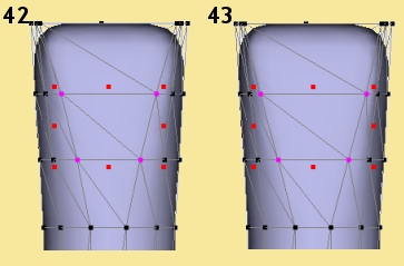
We now have a slight curvature to the edge of the 'blade' - to straighten this, select the points shown in Pic 42 (front and back) and use the Scale tool with Ctrl held to horizontally scale outwards slightly (Pic 43).


Switch to the Left view and select the points shown in Pic 44. Use the taper tool again to taper the top edge inwards as shown in Pic 45. Switch to the Top view (Pic 46). Notice how the sides of the blade are curved (see selected points) - we want this to be straight since the cross-section of the blade is rectangular at this point. One way to do this is to select the points on one side as shown then use the Scale tool - Ctrl pressed, drag one of the middle handles inwards as far as it will go - this will 'squeeze' the selection together to lie in one plane as shown in Pic 47. Repeat for the other side.


Back to a near Front view. Select the top set of faces and use the Bevel/Extrude tool to extrude 3 sections as shown in Pic 48. Switch to Front view (Pic 49) and use the taper tool to taper in the top of the screwdriver blade as seen in Pic 50. Switch to the Left view (Pic 51) and taper the selected points inwards at the top to give the almost sharp end of the blade (Pic 52).


Now to get the nice sharp edges of the blade. This can be done nicely in AoI using Smoothness control. Select the edges shown in Pic 53 (front and back). Click on Mesh -> Set Smoothness or press Ctrl-S to display the Set Smoothness dialogue. Enter a smoothness of 0 and click on OK to give the selected edges a sharp edge as shown in Pic 54.


Switch to Left view and select the points shown in Pic 55(front and back). Move them down as shown in Pic 56. Then select the points shown in Pic 57 and move down those a lesser amount to get a curve. Switch to Edge mode, select the curve we just made and set the smoothness of the edges to 0. The head of the blade should now look like that in Pic 59 - turning off the control mesh can be helpful for viewing the object more clearly (this can be toggled on/off via View -> Show -> Control Mesh).


That's the hard bit done. To complete the screwdriver, select the bottom set of faces and extrude them down almost to the full length and then again a small amount to get a sharper end.


TEXTURING AND RENDERING


Setting up the Scene

Before we begin the texturing and rendering, we need to set the scene up a little. Firstly, we need a surface for the screwdriver to sit on. A simple one can be made either using a very flat cube or a flat spline sheet. Create one and sit the screwdriver on it. Also create a point light close to the part you're texturing - that way we can see clealy the effects of texture changes.

Now, both the handle and the blade textures are going to be shiny, reflective ones. It is very important when using such textures that there is something in the environment to reflect. If you use a single colour background, reflective textures won't look right. So, either you need to create a whole lot of other stuff in your scene or, much more simply, you can use an image or a pattern as your background. HDRIs (High Dynamic Range Images) are the in-thing at the moment and for good reasons - they provide just the sort of background image you need in this situation and they're also good for creating natural lighting by using them as the light source in a scene ('image-based lighting').

So, I suggest you get hold of a number of HDR images - there are several places on the internet that you can find them. You can make your own - but you need reasonably specialised equipment to do so. The one I used for this tutorial can be found at http://www.debevec.org/Probes/ and is called 'Overcast Breezeway, Soda Hall' - this is a .jpg version of it (not many image packages will display .hdr images - there is a program called 'HDR Shop' that will display them (and much more besides) and is freely downloadable from http://www.debevec.org/HDRShop/):


To put this onto the background environment, you first need to create a texture with it. I tend to do this as a procedural 2D texture as this allows control over brightness etc. So create a new procedural 2D texture via Scene -> Textures. Click on New, enter a name of your choice for the texture, change the Type to Procedural 2D and click OK. This then displays the procedure editor, part of which is shown below:


Click on Insert -> Patterns -> Image to add an Image module to the editor's 'canvas'. Now double-click on the module to bring up a dialogue in which you can set the image (as well as its tiling and mirroring). Click on the blank square at the top to display thumbnails of images already in the scene - or not, as you shouldn't have yet. Click on 'Load' and select the HDR image - this should now be displayed on the thumbnail list. Click Done and the image should now appear in the previously blank image box in the Set Image dialogue. Now click OK to return to the procedure editor where the image should now be displayed in the image module as shown on the right.


I usually then attach a colour scale module (Insert -> Color Functions -> Scale) as shown. Connect a number module (Insert -> Values -> Number) as shown and the output of the colour scale to the Diffuse box. Now, by changing the number (double-click to change), you can alter the brightness of the image - I've actually left it at 1.0 here but it is now easy at a later stage to alter it if I need to.

Now go to Scene -> Environment to open the Environment dialogue. Click on the arrow to the right of Environment and choose Texture - Diffuse then click on the Set button to select the texture that we just made. We also need to map it correctly so click on Edit Mapping. The HDR image that we are using is in such a geometry that we use Projection Mapping - other HDRIs that you come across may need mapping Spherically (see the manual for more details on spherical mapping). So, leave the mapping set to Projection and alter the scaling - set both X and Y scale to 4.0 so that the image wraps around the sphere well and leave everything else as it is. Click OK on the dialogues in turn to return to the scene. OK, now we have the HDRI map as a background and our reflective textures are going to look realistic as a result.


Texturing the Handle

The handle of the screwdriver is a hard, yellow, shiny, reflective, transparent plastic. For extra realism, we're also going to have some scratches and hand-grease smears - all done with procedural textures.

First off, create a Procedural 2D texture and enter the procedure editor. Now when setting up textures and working out various aspects of it, it is often best to start simple.

So to start insert a Color module (Insert -> Values -> Color), double-click on it to open a colour chooser dialogue and create a yellowish colour like . The handle is also going to be reflective, so later we're going to use the Specularity parameter but for now we'll just use the Shininess property. This property is actually a cheat to simulate the reflection you would get on a surface from a light source - if you're using standard light sources in a scene, you will need Shininess as well as Specularity (which is true reflection of the surroundings) because light sources are not visible and therefore are not reflected. When using a HDR image, this image usually contains the lights as part of the image and so they will be reflected in a surface with specularity. So, later on we will switch from using Shininess to using only Specularity. But, for now, create a Number module and plug its output into the Shininess box. Double-click the Number module and enter a value of 0.8. Click OK to accept the texture and assign the texture to the handle (click right on the handle in the Object List and select Set Texture, choose the texture and click OK).

You should get the result on the right: This is fine as a basic hard yellow plastic.


Now to add some realism to the texture - some scratches. We're going to do this in the same texture so open up that texture in the procedure editor (Scene -> Textures then select the texture from the list and press Edit). The scratches are going to be applied as variations in the Bump Height property. Now, we want to scratches to be positioned randomly. A good way to acheive random placement in procedural textures is to use the Cells pattern. The Cells pattern is often used for irregular shaped regions over a surface but this pattern starts from a set of randomly positioned points which is what we need. So, bring a Cells pattern module onto the canvas via Insert -> Patterns -> Cells. Note that there are 3 output of the Cells module - the top one would be the one used for creating the irregular shaped regions I mentioned earlier. The other two are the distances from each point on the surface to the nearest or next nearest random point. If we tested these values to see if they were less than a certain value, we could create circles centred around point in the random set of points. That's what we're sort of doing here except that instead of circles we want long thin shapes to represent the scratches. So, let's put this first stage into practice - add a Greater Than module (Insert -> Functions -> Greater Than) and a Number module and join them up like this:


I often find it useful when trying out the effect of variations in the texture to use a colour map temporarily. Fo example, here we're trying to create an effect in the Bump Map which may be too subtle to see properly - so create a Custom Color module (Insert -> Color Functions -> Custom) and plug the output of the Greater Than module into that. Temporarily delete the link into the Diffuse box from your yellow colour and plug the output of the black/white colour map instead:


Hmm.. the preview shows us a plain white. In other words, the value coming out of the Greater Than function is 1 for all points on the surface. That's because we need to scale the random pattern of points down - it's too big. To scale it down, add a linear transform module (Insert -> Transforms -> Linear). Double-click it and set the Scale boxes for X, Y and Z to 20 - you should now see and speckly pattern on black dots on a white background. In terms of Bump Height, white indicates 'higher' areas than black - we want the scratches to be 'low' compared to the resr of the surface, i.e we want them towards the black end of the scale which is what we are getting here.


However black dots isn't what we're after. If we make one of the Scale factors small compared with the others, however, we can get stretched dots. Double-click the transform module again and change the Scale to X:1 Y:12 Z:12. These are values I arrived at after playing around for a while - quite often this is what you need to do to get the desired effect:


Just to soften the 'scratches' slightly, I've also added a Blur module (Insert -> Functions -> Blue). Plug the result of the Greater Than module into that before in enters the temporary colour map. The default blur value (0.05) is too much so add a Number module with value 0.005 as an input to the Blur module as shown below:


Now we'll apply the texture to the handle - we're going to do it again since we now have a pattern to map so we'll need to play around the the mapping. So, click right on the handle in the Object List and select Set Texture. The correct texture should already be selected so just click on Edit Mapping.

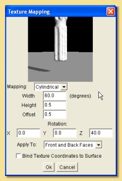
See the manual for a full description of what everything does. Basically we have 3 choices for wrapping the texture around the object; Projection, Cylindrical, Spherical. Because the shape of the screwdriver is essentially cylindrical, select that Cylindrical. You will then need to play around with the scaling and the position of the texture to get the scratches in the right place.

The Width and Height fields vary the scaling of the texture and the Offset moves it around. It can also be rotated by entering appropriate values lower down. Use the values in the image on the right or derive your own and click OK to set the texture.


Now go back to the procedural texture editor, get rid of the temporary black/white colour map and plug the output of the function into the Bump Height instead. Plug the yellow colour module back into the Diffuse box. Click OK to leave the procedure editor and render the scene - you should get something like this.


OK, now we're going to add some smears onto the surface which will represent wear and tear and sweat and grease for hands - yuk! This will have an adverse effect on the specularity/shininess of the handle so the smears will be represented by variations to these texture properties.

For this we're going to use a randomly varying pattern. There are 2 we could try: Noise or Turbulence and you could probably get good results with both. I used a Turbulence module (Insert -> Patterns -> Turbulence. Again, use my earlier tip with the black/white colour map to see the variation more clearly. Double-click the Turbulence module - there are 2 parameters that we can use to affect the pattern; Amplitude which is the size of the variation - leave this at 1.0, and Octaves which, together with the Noise input to the module, determines the 'detail' in the pattern. We want quite a smeary smooth noise, so take this down to 2. Using the temporary color map trick, you should get the below result:


In this case, values near zero (black) have less reflection/shininess than those nearer 1 (white). White areas represent 100% reflectivity. So, that looks pretty good - you could test the mapping by doing a test render but I know it will look good. When happy, plug the output of the Turbulence into the Shininess property in place of the 0.8 value module and plug the yellow colour module back into the Diffuse. Rendering now should give the result below:


You can see that certain areas have a matt quality as you might expect from wear/tear/grease etc.


Now to make it transparent. Re-enter the procedure editor. We're simply going to set a constant value for the transparency property. Insert a Number module and set it to 0.7 and plug the output into the Transparency box.

That makes it uniformly transparent but we also need to set the Transparent Color correctly - when light passes through the clear plastic it will pick up a yellow tint so add a Color module to the canvas, set it to a light yellow and plug it into the Transparent Color box.

While we're at it, delete the connection between the Turbulence module and the Shininess box and plug it into the Specularity box for the full effect.

The final texture is shown on the right and a test render should look like this:


We're almost there but it's missing something - distortion, i.e. light refraction through the handle. This is achieved via Materials rather than Textures. So, create a new Material via Scene -> Materials. Click on New, enter a name for it, leave the Type set to Uniform and click OK. This opens the Material dialogue as shown below:

See the manual for more details of all the settings. We're actually going to leave them all as they are except the Index of Refraction which will give us our distortion. Change this to about 1.5 for a hard plastic or glass material.

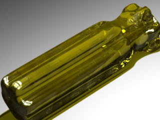
Set the material to the handle by right clicking on the handle on the Object List and selecting Set Material. Select the material and click OK. A final render should look like that below - that's the handle finished:


Texturing the Screwdriver Blade


The blade texture is a procedural 3D one - this differs from a 2D one in that the object appears to be carved out of the texture rather than the texture being wrapped around it. In fact, we're going to use 2 textures and created a layered texture from them.

Let's start with the underlying texture - this will be a rusty metal with some anisotropic specularity, i.e. the reflectiveness will vary non-uniformly across the surface - I want to get the sort of brushed metal look that you get on these types of screwdriver blades. So, create a new procedural 3D texture.

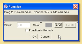
The first thing we'll do is create the Diffuse colour - insert a colour map (Insert -> Color Functions -> Custom) and double-click it to open the colour map editor. Click on the small arrow on the left of the colourbar to display the colour at that part of the map on the small rectangle identified as Color. To change this colour, click on the rectangle - this will open the colour chooser dialogue. I want to have a basic metallic grey here e.g. Hue-0.0, Saturation-0.0, Value-0.63. Click OK and then select the small arrow at the other end of the colourmap - set this colour to a dirty brown e.g. H-0.09, S-0.37, V-0.43. This gives a map which is a linear change between the 2 colours. However, I want a more sudden change between grey and brown so add another colour to the map by clicking Add. This will add a new small arrow at the centre of the map - click on it and change the colour to the same grey as we set for the left side of the map (see right). Click OK and connect the output to the Diffuse box.


All you will see on the preview at this stage is a plain grey. That's because we haven't told AoI how we want the colourmap to be applied - there is no input to the colourmap. What we want is a noise type pattern of brown blotches on grey so we'll use the noise pattern. Add a Noise pattern module to the canvas via Insert -> Patterns -> Noise and connect its output to the colour map input.

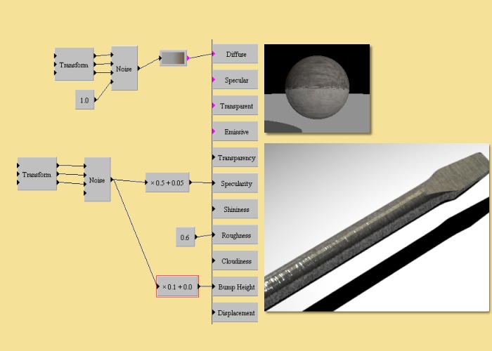
You should now see some brown appear on the preview. At this stage the brown is a bit too wishy-washy. To improve this, increase the noise in the pattern by adding a Number module, setting it to 1.0 and plugging it into the noise input (the bottom input) of the Noise module. Finally reduce the scale of the pattern by adding a Linear Transform module, setting the X, Y and Z scales to 10.0 and connecting all 3 inputs to the Noise module as shown on the right:


Now let's add some specularity to the metal. First off, just try setting a constant specularity by inserting a Number module, setting it to 0.5 and connecting it to the Specularity box. We also want the surface to be rough so that specular highlights are spread out and reflections are blurred - to achieve this, add a Number module, set to 0.6 and plug it into the Roughness property box.

Assign the texture to the screwdriver blade and use the Edit Mapping dialogue to get the right scale for the pattern. Due to the long, thin nature of the object, it will difficult to assess this in the Edit Mapping preview so you will need to do a series of test renders to get it right. I set the X,Y and Z scaling to 0.2 to get the result on the right:


Now we're going to add some anisotropy to the texture to get the brushed metal look. We'll do this is 2 ways; first by creating some fine stretched bumps. Add a Noise pattern module and plug it into the Bump Height box. Reduce and stretch the scaling of the noise pattern by adding a Linear Transform module, setting the its Scale to X:1, Y:20, Z:20, and plugging all 3 outputs into the 3 inputs of the Noise pattern. This compresses the pattern along Y and Z but not X.

At this stage the preview shows that the bumps are too great. To reduce them, create a Scale/Shift module (Insert -> Functions -> Scale/Shift), double-click it and set the 'x' box to 0.1. This reduces the bump height 10 times.

Your texture should now look like that on the right, with the test render also shown. Notice how it differs from the previous render, especially where the bumps catch the light from the HDR image.


To emphasise the anisotropy further, we're going to change from a uniform specularity to one that varies in the same way that the bump map does. This is simply done; we're just going to take another output from the Noise pattern we used for the Bump Height.

First create another Scale/Shift module so that we can scale down the output (as this has an amplitude of 1 and this is too high). Plug the output of the Noise pattern into the Scale/Shift module, alter the values of the Scale/Shift to give 'x 0.5 + 0.05' and connect the output into the Specularity box in place of the 0.5 we had from before. This Scale value of 0.5 means that the specularity will vary between 0 and 0.5 depending on the value of the Noise pattern at a particular point on the surface. The Shift value of 0.05 will mean that all parts of the surface will have some reflection, even if the Noise pattern is zero there.

The final base texture is shown on the right, together with a test render. You can see that we have a nice battered, scratched metal texture.


Just to complete the overall texture, we'll make the screwdriver blade look even more abused by adding some more rusty dirt in a new texture layer.

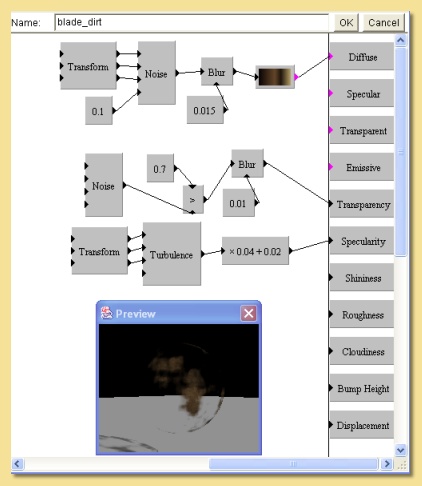
So, create a new procedural 3D texture. The first thing to do is get the diffuse colour looking right. Create a custom colour module and double-click to edit the colours in the map.

The colour map on the right shows the colours I used. Connect the output of the Custom module into the Diffuse box.


Now, we're going to use a Noise pattern module as the basis of the colour pattern. So, create a Noise module and connect it to the input of the Custom color module. I wanted it to vary quite a bit so I increased the Amplitude of the Noise module to 2.0 (double- click the Noise module to alter it). Set the Octaves to 3.0. We want a small scale noise pattern so insert a Linear Transform module and connect it to the input of the Noise pattern. Alter the scaling of the Transform module to X:20, Y:20, Z:20. Just to smooth the noise slightly, add a Number module to plug into the noise input of the Noise module and set it to 0.1. To further smooth the pattern, add a Blur module (Insert -> Functions -> Blur), disconnect the link between the Noise pattern and the colour map and connect the output of the Noise to the Blur instead, then the Blur to the colourmap - the Blur is a little too much so alter the blurring factor by adding a Number module set to 0.015 as the Blur input of the Blur pattern.


Now, this texture is going to be applied as an overlay on the other blade texture we made. For this to work, we need to make some of this texture transparent so that the other texture will show through. We want this transparency to be a random pattern so we're going to use the Noise module again. So, create a Noise module with the default settings. To get this function to pick areas of the texture to make transparent in a reasonably discrete way, I have used the Greater Than function in a similar way as we did to get the scratches on the handle. This time we want areas where the Noise pattern is below a certain value to be set to 1 and everywhere else to be set to 0 - when connected to the Transparency box, this will create discrete transparent areas. So, insert a Greater Than module, plug the output of the Noise module into the bottom input and a Number module set to 0.7 into the top. If you try plugging the output of the Greater Than function into the Transparency, the 'discreteness' is a little too much, so use a Blur function between to soften it.


OK, almost done. The last thing is to add a small amount of specularity to the rusty dirt. This I did using a Turbulence module scaled with a Linear Transform (scaling X:10, Y:10, Z:10) and the output scaled/shifted as shown below:


Right, now to apply the textures to the blade object. Select the object and click right in the Object List to select Set Texture. In the dialogue that comes up, select alter the setting at the top from Simple Texture to Layered Texture. The dialogue will change to that below:


Select the 2 blade textures from the left list and click Add each time to bring them into the list in the centre of the dialogue as shown above. Make sure the Blade dirt texture is above the main Blade texture in this list - if it's not then use the Move Down or Move Up to get it there. Click on the Blade dirt texture and set the Blending Mode to Overlay. Now select each texture in the central list in turn and select Edit Mapping to map the textures appropriately - I used a scaling of 0.2 for X, Y and Z for the main Blade texture and a scaling of 0.5 for X, Y and Z for the dirt texture. In addition I altered the Centre of the dirt texture to move the dirt to the place I wanted it.

The final render of the blade should look similar to this:


...and the final thing like this.